CadQuery vs OpenSCAD for AI-generated functional parts
We gave six AI agents the same three printable parts to model, three in CadQuery and three in OpenSCAD, then verified every mesh independently. Both toolchains shipped. The difference is in how they fail.
ModelRift generates OpenSCAD for every model on the platform. That choice is worth re-testing occasionally, so we ran a controlled comparison against the most credible alternative for code-first CAD: CadQuery, a Python library on top of the OpenCascade B-rep kernel.
The question was narrow: which one can an AI agent drive to a correct, printable, functional part with nobody watching? How pleasant each is to write by hand did not come into it.
Six agents, three tasks, two tools. Every resulting STL was then checked by a parser that trusts neither tool.
All six parts came out printable. Capability turned out to be the boring part of the answer. Where the two diverge is in how they fail.
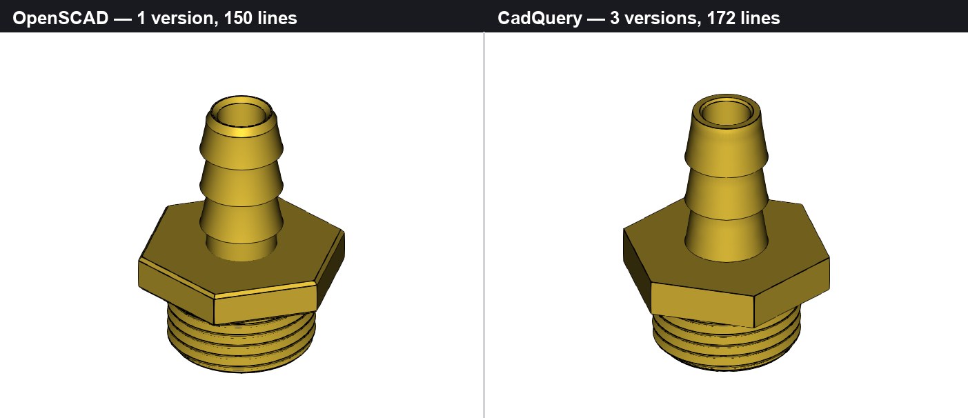
The hardest task in the set, solved by both tools. OpenSCAD on the left, CadQuery on the right.
Setup
All six runs were driven by Claude Opus 5 (1M context) through Claude Code. Each cell ran as a separate general-purpose subagent inheriting that same model, with no cross-talk between them. One agent per cell, so part of the spread below is agent variance rather than tool difference. Tool versions were CadQuery 2.8.0 on Python 3.14 and OpenSCAD 2026.06.12, both on an M-series Mac.
The OpenSCAD side ran on our own openscad-skill, the agent skill we publish and use in house. It covers file and version naming, the render-inspect-fix QA loop, camera presets for CLI previews, cross-section debugging, and Customizer syntax.
For CadQuery we ported that skill operation by operation, keeping the same structure and replacing only what has no OpenSCAD equivalent. CadQuery has no CLI renderer, so the port needed a small offscreen renderer written for it, plus B-rep validity metrics in place of the CSG status line. Both files then got the same 3D-printing design rules, wall thickness, clearances and overhangs, so neither side was handed advice the other lacked. Sizes landed at 12.4 KB for OpenSCAD and 13.1 KB for CadQuery.
One asymmetry survived: the CadQuery file carries an API cheatsheet the OpenSCAD file does not need, because the model already knows OpenSCAD syntax well. That helps CadQuery on syntax and does nothing for it on geometry.
Each agent was capped at 12 versions, told never to fake success, and required to report every failure with its verbatim error text. They ran unattended.
We did not take the agents’ word for anything. Every final STL went through a parser that reads the file directly and reports triangle count, bounding box, volume, watertightness, non-manifold and boundary edges, flipped faces, and connected components. That turned out to matter more than we expected, for reasons further down.
The three tasks
Both agents on a task got the same text, with no tool-specific hints.
The simple one, T1, was a wall-mounted shelf L-bracket: two plates at 90 degrees, 4 thick, two triangular gussets, two countersunk holes for flat-head screws at 90 degrees and 9 head diameter, two plain holes, R3 on the outer vertical corners, R4 fillet on the inner corner, printable without supports.
T2 raised the stakes to a two-part snap-fit enclosure for a 50 x 26 PCB. Walls 2, cavity clearance 0.4 per side, four M2 posts, a 9.5 x 3.5 USB-C cutout, a separate lid with a peripheral lip at 0.2 clearance and working snaps, five vent slots. The two parts had to actually fit.
T3 was the hard one: an M24x2 threaded hose-barb adapter with a hex flange 30 across flats, a real helical thread 12 long, a 25 long barb carrying three barbs for 12 ID hose, and an 8 through-channel. The spec explicitly banned stacked rings. The thread had to be true helical geometry.
Results
| T1 OpenSCAD | T1 CadQuery | T2 OpenSCAD | T2 CadQuery | T3 OpenSCAD | T3 CadQuery | |
|---|---|---|---|---|---|---|
| Versions | 2 | 3 | 8 | 5 | 1 | 3 |
| Lines of code | 103 | 135 | 220 | 266 | 150 | 172 |
| Errors the tool raised | 1 | 4 | 0 | 0 | 1 | 1 |
| Silent wrong geometry | 0 | 0 | 5 | 3 | 0 | 1 |
| Agent wall-clock | 461 s | 562 s | 1058 s | 909 s | 542 s | 935 s |
| Agent tokens | 77 k | 89 k | 138 k | 139 k | 82 k | 119 k |
| Geometry recompute | 12 ms | 1.56 s | 16 ms | 1.93 s | 43 ms | 1.95 s |
| Final STL verdict | clean | clean | clean | clean | clean | clean |
Summed across the three tasks:
| OpenSCAD | CadQuery | |
|---|---|---|
| Versions | 11 | 11 |
| Lines of code | 473 | 573 |
| Errors the tool raised | 2 | 5 |
| Silent wrong geometry | 5 | 4 |
| Agent wall-clock | 2061 s | 2406 s |
| Agent tokens | 297 k | 347 k |
“Clean” means watertight, one connected component, zero non-manifold or boundary edges, sitting on z = 0, measured from the file rather than reported by the tool that wrote it.
Iteration count came out identical at 11 versions each. So did the broad shape of the effort. What differs is the character of the problems each agent hit.
T1: the simple bracket
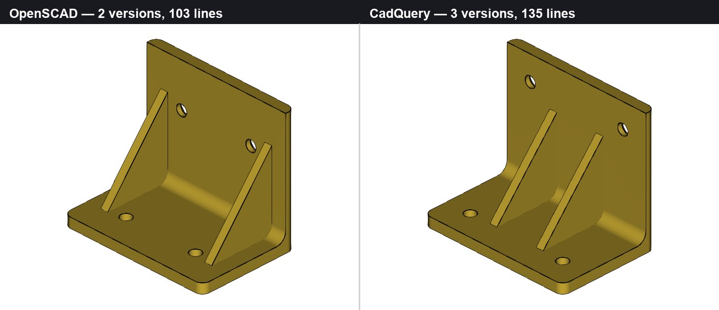
Both correct, shown from the inner corner so the gussets are visible. The visible difference is interpretation: the spec left gusset size and inset open.
Rounding the four outer corners separates the two models of the world cleanly. OpenSCAD rounds a 2D profile and extrudes it, so the operation does not care how the solid was assembled:
module corner_mask() {
    translate([0, 0, -eps]) linear_extrude(vert_h + 2*eps)
        offset(r = corner_r) offset(delta = -corner_r) square([plate_w, horiz_d]);
}
CadQuery has to name the four edges first, and naming is the hard part:
result = result.edges("|Z").edges(
    BoxSelector((-WIDTH, -EPS, -EPS), (WIDTH, EPS, V_HEIGHT + EPS))
    + BoxSelector((-WIDTH, H_DEPTH - EPS, -EPS), (WIDTH, H_DEPTH + EPS, V_HEIGHT + EPS))
).fillet(R_OUTER)
OpenSCAD compiled correct geometry on the first attempt and finished in two versions. CadQuery spent about a third of its run on a single error: .fillet(3.0) failed with BRep_API: command not done, a message that names neither the edge nor the radius. The agent had to bisect by hand to discover the cause, which turned out to be arithmetic: two R3 fillets do not fit in a 4 mm wall.
T2: two parts that must fit
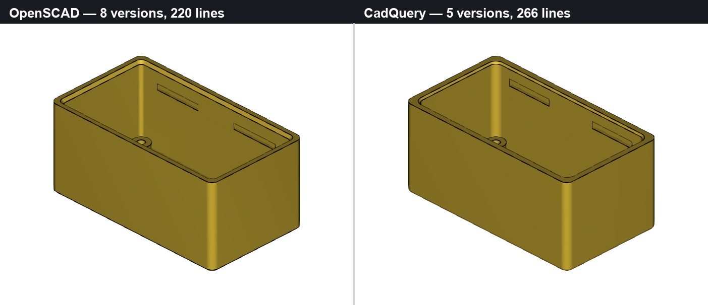
Both agents derived the same 54.8 x 30.8 x 25.0 mm box from the clearance stack-up.
This is where CadQuery’s parameter chain earned its keep. Changing the lip depth moved rim, plate, slots, groove and barb together, because each dimension is derived rather than typed twice. That kind of dimension chain is the same thing a good parametric UI exposes to the user, which we wrote about in Building a better OpenSCAD customizer. CadQuery has no Customizer equivalent, so the constants block is the entire parameter interface.
More interesting is how each side checked the fit. OpenSCAD prints numbers for someone to read:
echo(str("cavity LxW = ", cav_l, " x ", cav_w, " (clearance/side ", pcb_clr, ")"));CadQuery asserts, and the build stops when the assertion is false:
assert BOX.val().intersect(LID.val()).Volume() < 1e-6, "box and lid interfere"An echo only helps if somebody reads it. An assert fails the build on its own. For unattended generation that gap is most of the story.
OpenSCAD needed eight versions to CadQuery’s five, and three of those eight went to boolean hygiene rather than design: cleaning up slivers thrown off by tangent and coincident faces.
T3: the real thread
The hard task produced the biggest upset. OpenSCAD finished in one version, correct on the first compile, in 43 ms, with no library.
OpenSCAD has no sweep operation, so the agent wrote the helix as raw vertex and face arithmetic: one four-point ISO profile, 96 sections per turn, emitted as a single polyhedron. There are no guardrails in this code at all. Get the winding order wrong and the tool says nothing.
module helical_thread(turns, z0) {
    prof = [ [r_in, -flank_hz], [r_maj, -crest_hz],
             [r_maj, crest_hz], [r_in, flank_hz] ];
    n = round(turns * STEPS);
    pts = [ for (i = [0:n]) let(a = i * 360 / STEPS,
                                zo = z0 + i * thread_pitch / STEPS)
                for (j = [0:3])
                    [ prof[j][0] * cos(a), prof[j][0] * sin(a), prof[j][1] + zo ] ];
    fcs = concat(
        [ [3, 2, 1, 0] ],
        [ for (i = [0:n-1]) for (j = [0:3]) let(k = (j + 1) % 4)
              [ 4*i + j, 4*i + k, 4*(i+1) + k, 4*(i+1) + j ] ],
        [ [4*n + 0, 4*n + 1, 4*n + 2, 4*n + 3] ]
    );
    polyhedron(points = pts, faces = fcs, convexity = 8);
}
The agent also pre-empted the classic thread trap before writing a line: an ISO tooth spans exactly one pitch, so consecutive root flats land coplanar and the union goes bad. It sank the swept profile below the minor radius so the helix crosses the core instead of touching it. That is why the boolean was a non-event.
CadQuery expresses the same geometry in six readable lines, and that part worked first try:
helix = cq.Wire.makeHelix(pitch=THREAD_P, height=h, radius=R_ROOT, center=(0, 0, z0))
prof = (cq.Workplane("XZ", origin=(0, 0, z0)).center(R_ROOT, 0)
        .polyline(thread_profile_points()).close())
ridge = prof.sweep(path, isFrenet=True)

core = cq.Workplane("XY", origin=(0, 0, z0)).circle(R_ROOT).extrude(h)
rod = core.union(ridge)
The failure came on the last line, and it is the one result that changed how we think about the QA loop.
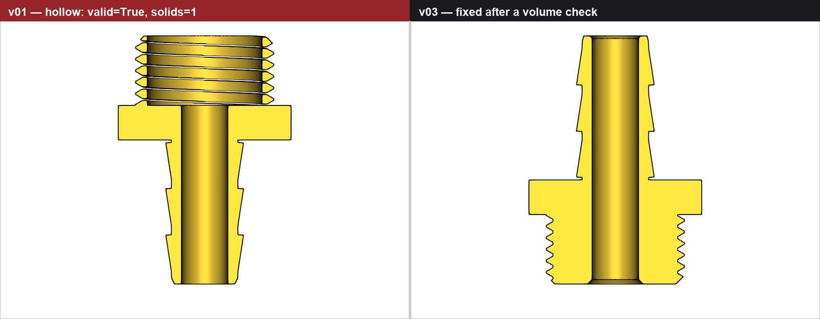
CadQuery T3 version 1 on the left. The threaded section is nothing but floating helical turns.
union() silently discarded the core cylinder because the thread root sat exactly on the core radius. Exact tangency along a helical curve, and OCCT dropped a solid without a word. From the outside the part looked perfect. The agent read four renders without noticing. What caught it was a volume measurement: 7065 mm³ where 10323 was expected.
Worse, the broken part reported valid=True and solids=1. Raising the boolean tolerance to 1e-3 produced a solid of negative volume that also reported valid=True.
OpenSCAD is not innocent here either. In T2 its Manifold backend certified Status: NoError for an STL carrying 4 non-manifold edges and 60 zero-area triangles. Neither tool’s self-report is the last word, which is why we parsed every mesh ourselves.
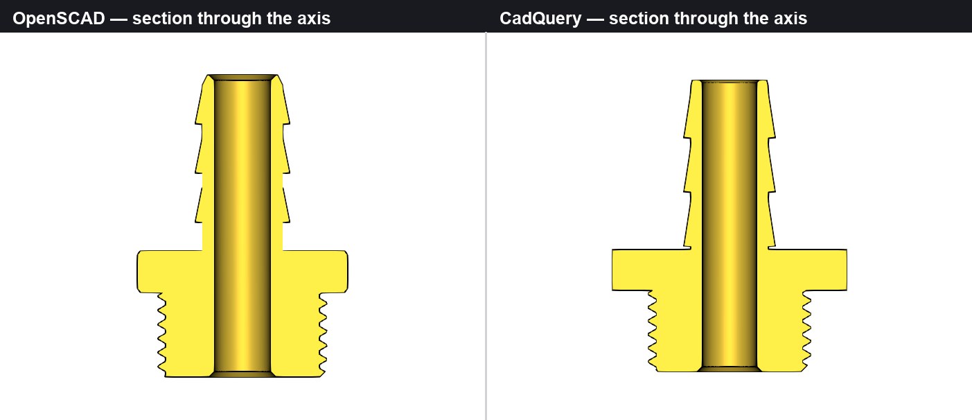
Both finished threads. Crests on the left flank sit half a pitch off those on the right, which is the signature of a true single-start helix and the check that tells a real thread from stacked rings.
Download the parts
Here are the eight final meshes, exactly as the agents exported them, with no cleanup or repair from us. Binary STL, millimetres, oriented for printing with the part sitting on z = 0.
| Part | OpenSCAD | CadQuery |
|---|---|---|
| T1 shelf bracket | STL, 2660 tris | STL, 4232 tris |
| T2 enclosure box | STL, 2944 tris | STL, 14136 tris |
| T2 enclosure lid | STL, 2960 tris | STL, 1872 tris |
| T3 threaded adapter | STL, 10754 tris | STL, 13748 tris |
Every one of the eight is watertight, a single connected component, with zero non-manifold edges, zero boundary edges and zero flipped faces. Clearances assume FDM with a 0.4 nozzle, so each T2 pair should snap together as printed.
The triangle counts are worth a glance, and they do not favour one tool consistently. CadQuery’s box carries almost five times the triangles of the OpenSCAD box, while its lid has fewer. Mesh density here follows how much rounded detail each agent chose to add, not the kernel.
What we found
Renders caught nothing that mattered
This is the result we did not expect. Across six runs, images caught coarse blunders, like four mounting posts deleted by a cavity subtraction, and nothing subtle. Every defect that would have ruined a print was found by a number instead: a volume, an angle, an interference test, a strain calculation. In T3 the OpenSCAD agent had the opposite problem and nearly rejected correct geometry, because a thread close-up rendered in a way that looked wrong. Its own note was that the render was not sufficient evidence in either direction.
The failure modes are mirror images
CadQuery fails loudly and early. Its messages are poor, but an exception stops the run, and a stopped model cannot ship by accident. OpenSCAD fails silently and late: in T2 it reported no errors and no warnings across roughly 45 invocations while producing deleted posts, misplaced slots, and a corrupted export it had just certified as clean. For unattended generation, silent success is the more expensive failure.
CadQuery can be interrogated, OpenSCAD cannot
CadQuery answers questions about its own geometry. The T1 agent proved its countersink was 90 degrees and 9 across by reading the cone’s half-angle off the B-rep, then wired the spec into asserts that re-ran on every build. OpenSCAD has no way to query geometry, so both OpenSCAD agents independently wrote binary STL parsers, roughly as much code as the models themselves, to measure what they had built. It works, but it only sees the mesh after export, never the design.
Speed favours OpenSCAD, and it barely matters
Geometry recompute is 30 to 100 times faster, 16 ms against 1.9 s. Inside an agent loop dominated by model inference that is noise. It would matter for a live customizer or a large parameter sweep.
OpenSCAD renders have no concept of a part edge
After CSG there is only a triangle soup, so --view=edges draws the triangulation rather than an outline. CadQuery’s B-rep knows where two faces actually meet. Since images are the agent’s feedback channel, this was a real asymmetry in our setup, so we fixed it by rendering the exported STL and reconstructing outlines from the angle between adjacent faces.
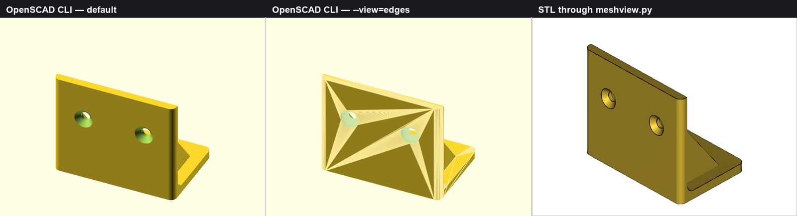
Same part, three renderers. Left: the CLI default, no outlines. Middle: --view=edges, which draws every facet. Right: feature-edge reconstruction from the STL, which also paints mesh defects in red. All six runs predate this fix.
Takeaways
Neither tool wins on output. Six clean printable parts, three from each.
What decides it is verifiability rather than expressiveness, and CadQuery leads there by a wider margin than the syntax difference suggests. Being able to ask the kernel what you just built, and to assert on the answer, is worth more in an agent loop than any amount of convenient syntax.
Task shape decides more than the tool does. Simple prismatic work went to OpenSCAD. Two parts that must mate went to CadQuery. The helical thread, the task that looked tailor-made for a B-rep kernel, went to OpenSCAD outright.
If a generation pipeline leans on screenshots, it leans on the one channel that caught nothing here. Numeric assertions are the thing to force: wall thickness, clearance, interference volume, overhang angle.
Verify the mesh independently, because both toolchains certified geometry that was wrong. This is the same lesson the Pantheon benchmark produced from a different angle, where Codex looked strong in the preview loop but shipped an STL with geometry problems around the portico roof. Preview and export are not the same thing. For anything going to print, the exported mesh needs its own inspection pass.
Caveats
One agent per cell, so some of the spread is agent variance rather than tool difference.
BOSL2 was deliberately not used. A library-assisted OpenSCAD run would likely change T2 and T3 substantially.
All six runs predate the outline renderer, so the visual channel was uneven while they ran.
This measured construction only. Nobody measured the harder skill, which is repairing a model somebody else broke.
What this means for ModelRift
We are staying on OpenSCAD, and this benchmark sharpened why rather than changing the answer. The original reasons still hold: a compact text format an LLM can write directly, safe sandboxing, and fast rendering, all covered in Why we built ModelRift on OpenSCAD. CadQuery’s advantage is real but sits mostly in verification, and verification is something we can add around OpenSCAD. Its disadvantages are structural for our case: a Python runtime per session instead of a WASM sandbox, two-second rebuilds instead of 16 ms, and no clean multi-object color export of the kind we built for multicolor 3MF.
The more useful finding is about feedback. The Pantheon benchmark ended on the observation that autonomous generation is not the right workflow yet, and that Annotation Mode, where you draw on a render and hand it back to the AI, is what makes spatial iteration work. This run adds a boundary to that. Visual feedback is the right tool for massing, proportion, and “the column is in the wrong place”. It is the wrong tool for wall thickness, clearance, and whether a boolean quietly deleted half your part. Those need numbers, and the agent has to be made to look at them.
Two changes are already going back into the published OpenSCAD skill. The feature-edge renderer above, so agents get previews with real part outlines instead of triangulation. And a numeric check pass the agent has to run before it can call a model finished: wall thickness, clearances, interference, and a mesh audit that does not ask the tool whether it did a good job.